
Enabling Better Products
Using 3-D modeling tools, we design, model and verify products to provide optimum high-speed performance, to help give you the competitive advantage.
Experienced Design, Documented Solutions, and Signal Integrity. Our experience in component-level simulation has enabled us to continue to provide industry-leading electrical models. As an active participant in industry-wide activities, we provide technical references and innovative solutions for a variety of system design challenges. We recognize that signal integrity continues to be a growing industry driver in high-speed designs. We are committed to pioneering new products and tools that meet the growing demand. Our signal integrity team has the expertise to engineer, layout, and build your proprietary high-speed digital systems. We have built numerous reference designs, including full system design and layout for finalized products for OEM, ODM, and component companies. Since our backplanes and interconnection systems run at gigabit speeds that can present unique challenges to designers, our proprietary broadband lossy-line models give more accurate insight into the influence of skin effect and dielectric losses on waveforms. This means we can help optimize your gigabit design based on the performance of actual devices. Additionally, we have worked closely with leading semiconductor vendors to characterize signals, identify noise levels, and define requirements for noise margins in the interconnection system. Our signal integrity team maintains an extensive library of high speed connector models – and we offers test capability to 67GHz, using advanced calibration and de-embedding techniques. Our expertise separates us from the competition; we are ready to start working on your simulations.
Electrical Models
Choose Your Model
Documents Published in English
Model Information
Electrical expertise – at your service. High speed links need to be designed on time and on budget. This is where our signal integrity services can help. Our goal is to apply system-level expertise to design, simulate, and verify a system that meets your performance goals. We provide the modeling skills and techniques, assortment of proven tools and ground-breaking solutions, and an extensive library of product models that can streamline your engineering process. Accomplished in completing hundreds of system designs and experienced in system layout, design, and simulation, we are ready to go to work for your design.
S-Parameters
Contains a matrix of frequency based data. These models are extremely versatile and can be used in time-domain transforms to generate impedance, crosstalk, propagation delay and eye-patterns, or they can be used in frequency-domain simulations for throughput and crosstalk. All files are provided in Touchstone format, which is compatible with many simulation software packages.

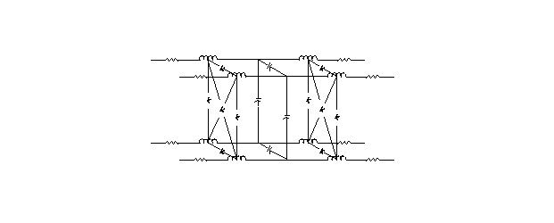
Multi Line Model (MLM)
A SPICE compatible representation of several lines of the connector, and includes the contact components, contact to contact couplings, and where applicable, includes contact to shield couplings, and inter-pad couplings. This results in a detailed model that can be used for simulating crosstalk and ground bounce in addition to the parameters analyzed with the Single Line Model (SLM).
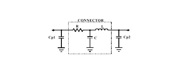
Single Line Model (SLM)
Represents the effects of one line of a connector wired appropriately for high speed signal transmission (typically near-by contacts grounded). The model includes the lumped elements representing the series resistance, "effective" inductance and the total capacitance for one line. It also includes the impedance (Z0 ) and propagation delay (tpd ) for the transmission line equivalent. This simplified model can be used for simulating reflections, time delays and skew, attenuation and signal transmission quality.
IBIS Models
Although we currently do not natively support IBIS models. Our models have been successfully converted into IBIS models or used in IBIS based tools. For help with IBIS models, visit he ANSI/EIA-656-A homepage.
CAD Mechanical Models
Looking for CAD Mechanical Models?
Credentials
Precision is critical in your industry. To ensure a successful implementation of your design, we team with silicon partners to develop simple, turn-key solutions.
Industry Standards
- OIF
- IEEE 802.3
- SAS (T10)
- InfiniBand
- Fibre Channel (T11)
- SFF
- PICMG
- SBB
- Open Compute
- JEDEC
- PCI-SIG
- USB IF
- VESA
- HDMI
- SD Card
Industry Multi-Source Agreements (MSAs)
- CDFP-MSA
- CFP-MSA
- microQSFP MSA
- HDSFF MSA
- COBO (Consortium for On-Board Optics)
- 25G Consortium